Monday, May 28, 2007

Setback


It's a damned shame.

The software company that provided an evaluation copy of its 3D CAD program has a name that is based on the Latin root word meaning 'free'. However, from the very beginning I was assaulted with solicitations for upgrades, and now that my 30-day trial is over, I find I am unable to use the program at all, despite a one-word assurance from an anonymous support tech that I would still be able to use it offline.

That was the one and only time I made use of but a single online feature, just to ask. If the one-word response had been 'no' instead of 'yes', I would've understood -- and then I would've made better use of my remaining time. Instead, I was misled.

Of course it is possible that the tech was pretty sure he or she was giving me the correct answer, just as it is possible that the answer was simply too short, and should've been accompanied by instructions. A third possibility is that the process is purposefully complicated and time-consuming, designed to discourage the very liberty the company's name implies. A fourth is that their online (site-related) software is inadequate; Possibility 4a is that the 'glitch' was intentional.

Perhaps I should have remembered sooner that the prefix 'a-' usually means 'not' (a + libre = 'not free').

At the moment I'm too annoyed to go looking for another program...


Phil Smith
May 28, 2007


...By the way? The new header image here was done using the GIMP, an image creation/manipulation program written for Linux but now available in a Windows version. Open-sourced, of course.


Phil Smith
May 29, 2007


_____

Monday, May 21, 2007

EXOVAN 2.0


This time I'm starting with the frame...


...and as the concept continues to evolve, the exoframe is no longer hanging out inches beyond the body. Instead (so far, only in my mind) it juts out like a metallic version of the framing on woodies from the 1920's and 30's. EXOVAN's framing is of square steel tubing, now turned at a 45
° angle.

This may make for a little more head-scratching during frame-up, but in the end makes the frame simpler and lighter. Yes, the idea of having bolt-on sections has been ABANDONED. The frame you see here is all welded...


Not that I know enough about structural rigidity, but looking at these images, right away I see a weak area in the floor that I'll have to address. Doesn't matter anyway, because what I care about is its function and appearance. Engineers will have their say.

This version of EXOVAN, once I add body panels, glass, and so forth, will be closer to the thing that will be built...

...and yes, one way or another, at least ONE example of EXOVAN WILL be built.

Dammit, it BEGS to be.


Phil Smith
May 21, 2007


UPDATE


Phil Smith
May 22, 2007

UPDATE 2


The evaluation period on my 3D CAD program expired today, but all that means is that I can no longer use online features. Not a problem -- hadn't been using them anyway. Above, you can see that I've begun to add panels after further frame reinforcements.

I know I've left a lot of things out, but I need to finish this 2nd draft before I start on the 3rd...


Phil Smith

May 23, 2007


_____

Saturday, May 12, 2007

Frame Job


- FIRST VIRTUAL MODEL OF EXOVAN COMPLETE -


It took some doing -- and these images do NOT represent the definitive version -- but here ya go. The virtual model was done as a single (intricate) 'part'. With the program I've been using, you get to select only one colour per part. A bit too late, I discovered (I think) that new parts can be created within an 'assembly'... I had thought that new parts had to be created separately before being joined together in an assembly -- my mistake. If you go to the
gallery on the Alibre Design website, you'll see what a hard time those designers/engineers would've had, creating parts in separate windows...


Above, you see EXOVAN in olive, camouflaged... The lights highlighted in bright green are for off-road use, too bright for streets and highways -- the two pairs of smaller ones are the main headlights. If you click on it (all of these are clickable for larger versions) you may be able to make out a double pair of even smaller lights, which are turn signals...


Extrusion 1 (the second step in the process, after a line drawing) is highlighted in red above, showing (in blue) where some of the side windows are.


Here I've made use of a different colour scheme to highlight panels in varying copper shades, to show glass area around the cockpit.


Note the cooling exhaust vents above the front track. This is a design feature I've used on previous flat-panel concepts, but in a slightly different location.

You may notice that the rear is more exposed to potential damage than the top, front, and sides. Somehow, along the way, I became quite fond of the 'naked' EXOVAN body -- and when it came down to it I couldn't bring myself to clutter up the rear. In any case this is not an area where one expects much damage in off-road situations, even rollovers.


I've left the tracks floating in space on purpose. Any suspension and steering linkages, or drivetrain details, might be misconstrued
-- as an automotive designer I am only PART engineer, so I won't try to fool anybody into believing I have everything figured out. Besides, this is only a quick-and-dirty first draft, merely an illustration of concept.

By the way, please don't tell me the exoframe just aft of the side portal is likely to get hung up on trees. If I were to do it over (and I probably will) I'd angle those sections out. Speaking of angles, the original concept called for sweeping curves in the exterior framing, which I may yet be able to produce with a 3D CAD program -- in a forthcoming virtual model.


A friend asked me a question recently about EXOVAN's steering. I can't answer about ratios, but it seems obvious that, unlike the Tesla Roadster, EXOVAN will require power assist (as will Tesla Motors' upcoming sports sedan, codenamed White Star). This assist, in the absence of an internal combustion engine (abbreviated ICE), must come from electric motors (plural -- EXOVAN features rear-steer). Toy remote-control vehicles have electric motors for steering. Suddenly I envisioned EXOVAN drivers being able to exit and pilot EXOVAN over particularly difficult terrain via remote control.

...And why not? Extreme rock-crawler drivers employ spotters to help guide them. Imagine being your own spotter, able to plainly see what your vehicle is up against while you yourself are at the controls. This could be done with a Wi-Fi laptop displaying all the views from EXOVAN's cameras (EXOVAN will feature only a pair of fisheye mirrors, the driver mainly relying on camera views).

Next: Lexus already has a car that will parallel-park itself. Imagine exiting the vehicle near your front door and watching it head off to its charging station by itself. You are confident that it will be waiting for you in the morning, charged and ready to go. The future is not only electric -- it is robotic as well.


In future posts, look for images manipulated with Photoshop to make EXOVAN look more real. You may also see some of my previous designs (I could be persuaded to scan old pencil sketches), and those discussions on a pair of timeless vehicles of others' design that I feel should be resurrected. However the very next one is likely to be about EXOVAN again...


Phil Smith
May 12, 2007


_____


Tuesday, May 8, 2007

Pincushion


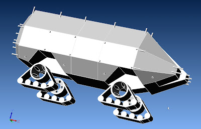
Today I managed to get started on the exoframe. For the image above, I chose the 'Shaded & Visible Edges' view in the CAD program -- now you can plainly see where the side portal is...

The image below shows the rear clearance lights that I added on just to get myself started. Also, you may be able to tell that the first two front-center roof posts are offset to the driver's side, just enough to allow clearance for the front hatch:


I had actually forgotten about that clearance issue the first time around with the roof posts, placing one of them in the center, directly between the side hatches
(the glass hatches slide up between the roof and the frame, and require a certain amount of room to do so); It was an easy fix, so no worries.

Next I'll have to figure out how to connect the dots, so to speak. If the resulting visible frame doesn't look beefy enough, remember there is also interior framing. With only the frame represented in these images, EXOVAN is sturdy enough to be driven (though this is not recommended). The bolt-on exterior sections will provide extra cross-bracing and rollover protection, and can be unbolted individually -- to access damaged panels underneath, or to repair or replace the frame sections themselves.

The main reason for these sections to be bolted on rather than welded amounts to a practicality issue in initial construction. If you weld the whole frame up first, good luck getting the body panels on...

You will notice there are no frame protrusions on the bottom of EXOVAN. It's one big skidplate under there -- with panels perhaps twice as thick as on other parts of the body -- allowing EXOVAN to slide over obstacles rather than get hung up on them.


EXOVAN is coming together, and once I'm satisfied enough with this first-draft model I'll grab a capture and Photoshop it for more detail and colour...


Phil Smith
May 8, 2007


Back to the Drawing Board

Shortly after publishing this
post, I began the maddening task of attempting to connect the through-body frame stubs with exterior frame sections. Much to my dismay, I found that a couple of key features for this kind of thing are left out of the free version of the 3D CAD program I'm using. At least I got the satisfaction, while browsing through the tutorials, of discovering that I'm already messing around on an 'advanced' level...

I kept at it anyway, enough to see EXOVAN partially clad in exterior framing, but finally called it a night. Went to bed with an inkling of how to finish my model with the (virtual) tools on hand...

...and I've been thinking about it since. What I'll need to do is to go back to an earlier saved version and create all the through-body extrusions all over again, this time with square sections instead of round ones. This will allow me to reposition some of them, and it will give me more flat surfaces -- surfaces to do drawings on, drawings to make extrusions from. Then I can either keep the square tubing or fillet the edges to make it round.

Since it will be better to use square tubing for the interior framing anyway, and since straight cuts will be simpler than round ones on the body panels, all the new through-body extrusions will be left square. That squareness will also come in handy when it's time to make the brackets for bolting exterior sections on.

Cooling still has to be addressed -- yes, even electric vehicles need cooling -- but I have an idea for duct openings that I think will be, um, pretty cool. Plus, they'll provide a mounting point for the headlights. Not sure if I'll do matching ones in the rear, and reposition the taillights into them...


Phil Smith
May 10, 2007

_____